Installation
Our Technology
Smart Guy R-164
Device using a direct method to measure, the guy wires tension. The connection must be thimble - turnbuckle. The displayed value represents the true guy wire tension. No other technology measures more accurately!
- The frame, consisting of two blocks connected by two threaded rods: the turnbuckle block with a round latch and connector for the electronic readout device and the thimble block with a groove in which the open end of the thimble is to sit;
- The thimble locking fork (the larger);
- The turnbuckle locking fork (the smaller); and
- The electronic readout device.
Smart Guy R-164 Installation
Procedure
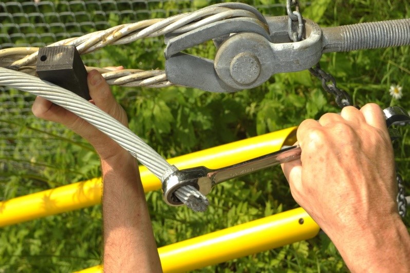
Step 1
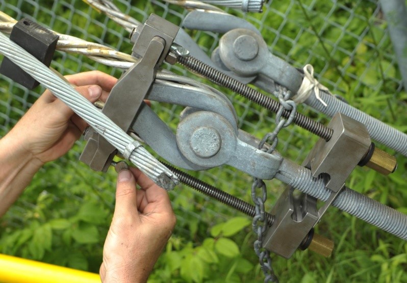
1. Using the ratchet key as a lever, lift the dead-end and install the rectangular rubber piece, to clear the way for frame installation. Position the Smart-Guy frame around the thimble tip and the shoulder of the turnbuckle jaw, from the far side of the joint as viewed by the installer. Install the device with Forks removed, placing the Latch around the Turnbuckle rod. To free up one hand, close the round latch on the turnbuckle block.
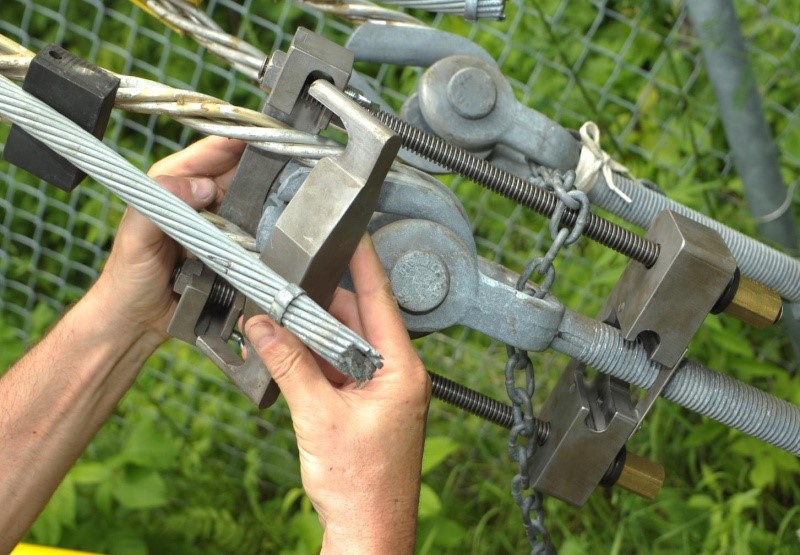
Step 2
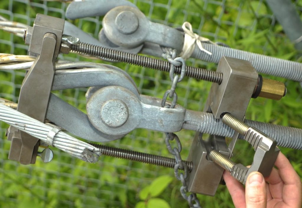
2. Slide the thimble locking fork into the side holes of the thimble block, as far as it will go so that both the thimble block and the fork rest properly against the thimble tip and grip it securely, then lock the winged locking screws.
Step 1
1. Using the ratchet key as a lever, lift the dead-end and install the rectangular rubber piece, to clear the way for frame installation. Position the Smart-Guy frame around the thimble tip and the shoulder of the turnbuckle jaw, from the far side of the joint as viewed by the installer. Install the device with Forks removed, placing the Latch around the Turnbuckle rod. To free up one hand, close the round latch on the turnbuckle block.
Step 2
2. Slide the thimble locking fork into the side holes of the thimble block, as far as it will go so that both the thimble block and the fork rest properly against the thimble tip and grip it securely, then lock the winged locking screws.
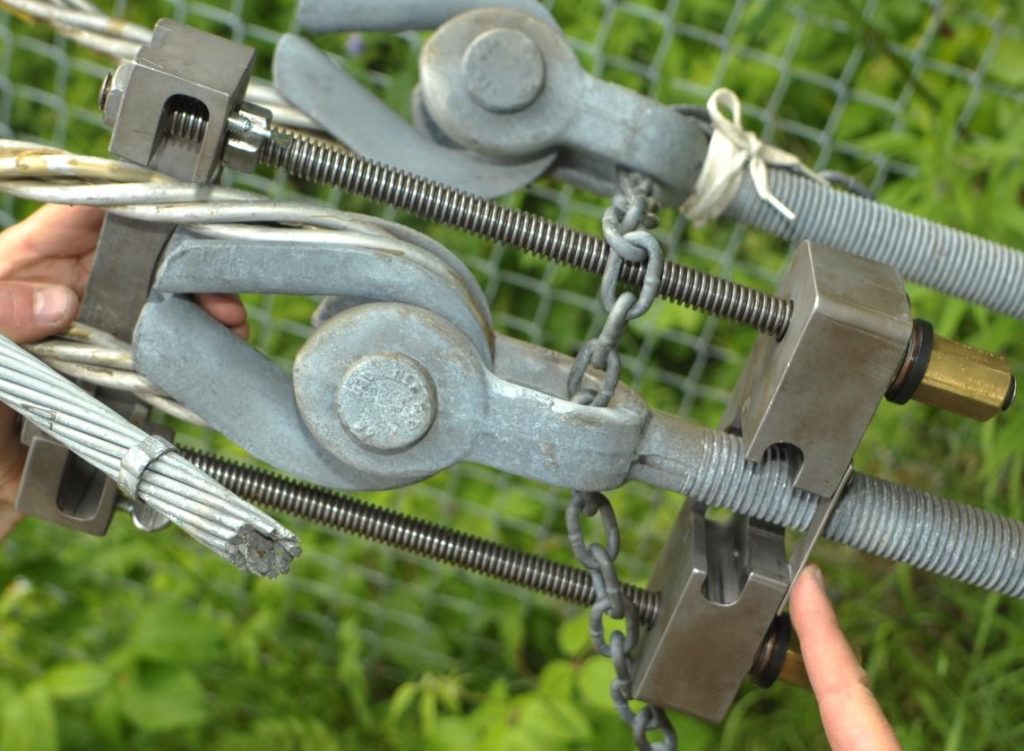
Step 3
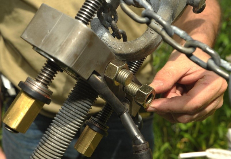
3. Slide the turnbuckle locking fork into the side holes of the turnbuckle block as far as it will go so that both the fork and the block are in proper contact with the shoulder of the turnbuckle jaw and lock the screws to prevent dislocation of the locking fork.
Step 4
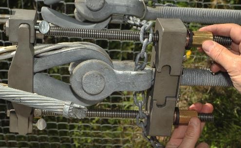
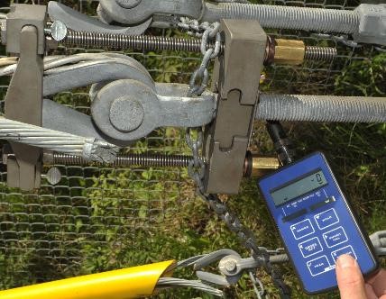
4. Hand tighten the bronze nuts on the threaded rods at the turnbuckle block until they will not turn freely and there is good contact and proper position between the frame and the thimble at one end and the shoulder of the turnbuckle jaw at the other end. Connect the electronic readout by screwing on the connector, switch it on and bring the readout to zero.
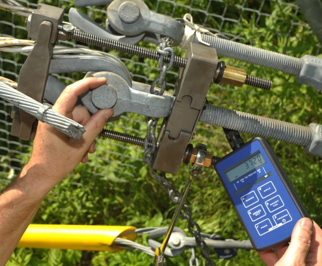
Step 5
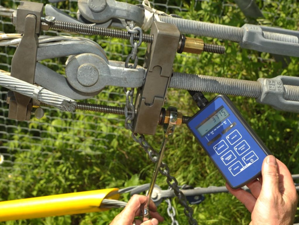
5. Use the ratchet key provided with the device, to tighten the bronze nuts, as uniformly on each side as possible, until the turnbuckle pin rotates freely or until there is the smallest possible gap between the turnbuckle pin or eye and the thimble; If the pin is, for some reason, locked against rotation or if there is no pin, because an eye bolt instead of a jaw bolt had been installed, pass a short length of special flat copper wire (provided in the box) between the thimble and the bolt or eye of the turnbuckle, to confirm that the load no longer passes between them, but through the rods of the Smart-Guy. Record the stable reading of the electronic readout device.
Step 3
3. Slide the turnbuckle locking fork into the side holes of the turnbuckle block as far as it will go so that both the fork and the block are in proper contact with the shoulder of the turnbuckle jaw and lock the screws to prevent dislocation of the locking fork.
Step 4
4. Hand tighten the bronze nuts on the threaded rods at the turnbuckle block until they will not turn freely and there is good contact and proper position between the frame and the thimble at one end and the shoulder of the turnbuckle jaw at the other end. Connect the electronic readout by screwing on the connector, switch it on and bring the readout to zero.
Step 5
5. Use the ratchet key provided with the device, to tighten the bronze nuts, as uniformly on each side as possible, until the turnbuckle pin rotates freely or until there is the smallest possible gap between the turnbuckle pin or eye and the thimble; If the pin is, for some reason, locked against rotation or if there is no pin, because an eye bolt instead of a jaw bolt had been installed, pass a short length of special flat copper wire (provided in the box) between the thimble and the bolt or eye of the turnbuckle, to confirm that the load no longer passes between them, but through the rods of the Smart-Guy. Record the stable reading of the electronic readout device.